The Benefits of Using PlantUML to Create Professional UML Diagrams

In the world of software architecture and design, clear and effective communication is paramount. One of the most powerful tools in a software architect's or developer's arsenal for conveying complex ideas and system structures is the Unified Modeling Language (UML). UML diagrams provide a standardized way to visualize and document various aspects of a software system. While there are several tools available for creating UML diagrams, PlantUML stands out as an excellent choice for both beginners and experienced architects. In this blog post, we'll explore the benefits of using PlantUML to create professional UML diagrams.
Simplicity and Ease of Use
One of the standout features of PlantUML is its simplicity and ease of use. Unlike some UML diagramming tools that can be complex and overwhelming, PlantUML relies on a straightforward and human-readable syntax. It uses plain text to define diagrams, making it accessible to those who may not be familiar with graphic design or intricate diagramming software.
Here's an example of a class diagram in PlantUML:
@startuml

skinparam linetype ortho
skinparam nodesep 100

class Customer {
  +id: int
  +name: string
  +email: string
  +getDetails(): string
}

class Order {
  +id: int
  +totalAmount: double
  +orderDate: date
  +createOrder(): void
}

Customer -- Order : places
@enduml
The simplicity of the syntax allows architects to focus on the design and relationships within the system rather than getting bogged down in the details of the tool itself.
Version Control and Collaboration
PlantUML diagrams are text-based, which means they can be easily version-controlled using tools like Git. This feature is invaluable for software development teams working collaboratively on a project. Architects can track changes to diagrams over time, collaborate with team members, and merge changes seamlessly, just like they do with code.
Additionally, because PlantUML diagrams are stored as text, they can be included in the project's documentation, ensuring that the architectural diagrams are always up-to-date and in sync with the codebase.
Cross-Platform Compatibility
PlantUML is platform-agnostic. It can run on various operating systems, including Windows, macOS, and Linux. This cross-platform compatibility ensures that architects can use their preferred development environment, making it easy to integrate PlantUML into their workflow.
Extensibility and Customization
While PlantUML provides a simple and concise syntax for creating UML diagrams, it also offers a wide range of customization options. Architects can tailor the appearance of their diagrams to match their project's style and requirements. This includes changing colors, fonts, and line styles to create visually appealing and consistent diagrams.
Support for Multiple UML Diagram Types
PlantUML supports various UML diagram types, including:
- Class diagrams
- Use case diagrams
- Activity diagrams
- Component diagrams
- Database ER diagrams
- C4 model diagrams
- And more...
Integration with Popular Tools
PlantUML can be integrated with popular text editors, development environments, and documentation generators. This integration streamlines the diagram creation process and ensures that architects can work efficiently within their preferred tools. Some popular integrations include Visual Studio Code extensions and support for Markdown-based documentation.
Open Source and Community Support
PlantUML is open source, which means it's continually evolving thanks to contributions from a vibrant community of users and developers. Bugs are fixed promptly, new features are added regularly, and the tool enjoys excellent documentation and user support. This open and collaborative environment ensures that PlantUML remains a reliable choice for software architects and developers.
Examples
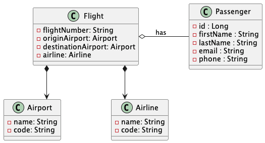
Class Diagram
@startuml

skinparam linetype ortho
skinparam nodesep 100

class Airport {
  - name: String
  - code: String
}

class Airline {
  - name: String
  - code: String
}

class Flight {
  - flightNumber: String
  - originAirport: Airport
  - destinationAirport: Airport
  - airline: Airline
}

class Passenger {
  - id : Long
  - firstName : String
  - lastName : String
  - email : String
  - phone : String
}

Flight *--> Airport
Flight *--> Airline
Flight o-right- Passenger : has

@enduml
Results:

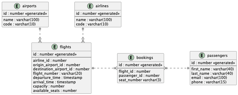
Database ER Diagram
@startuml

skinparam linetype ortho
skinparam nodesep 100

entity "flights" as e01 {
  id : number <<generated>>
  --
  airline_id : number
  origin_airport_id : number
  destination_airport_id : number
  flight_number : varchar(20)
  departure_time : timestamp
  arrival_time : timestamp
  capacity : number
  available_seats : number
}

entity "airlines" as e02 {
  id : number <<generated>>
  --
  name : varchar(100)
  code : varchar(10)
}

entity "airports" as e03 {
  id : number <<generated>>
  --
  name : varchar(100)
  code : varchar(10)
}

entity "passengers" as e04 {
  id : number <<generated>>
  --
  first_name : varchar(40)
  last_name : varchar(40)
  email : varchar(100)
  phone : varchar(15)
}

entity "bookings" as e05 {
  id : number <<generated>>
  --
  flight_id : number
  passenger_id : number
  seat_number varchar(3)
}

e01 }o.up.|| e02
e01 }o.up.|| e03
e01 ||.right.|{ e05
e05 }|.right.|| e04

@enduml
Results:

